Egg Transport Vehicle
The Problem
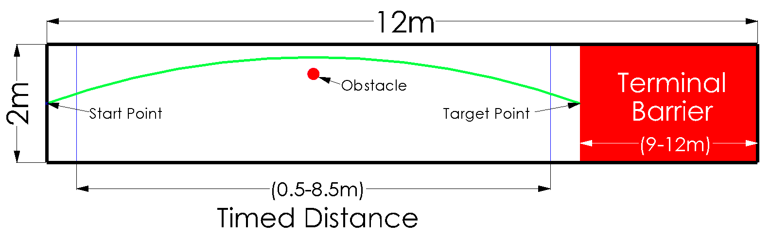
Design, build, and test a mechanical device that uses the energy from a falling mass to transport an egg along a track as quickly as possible and stop as close to the center of a terminal barrier without cracking the egg. The barrier's location is unknown prior to the competition and can be between 9-12m. Competitors who complete the bonus of traveling around the predetermined obstacle will be placed higher than those who travel in a straight line.
Constraints:
- All energy must come from a falling mass <= 2kg
- The system’s dimensions must be no greater than: W = 0.75m, L = 1.0m, H = 1.0m
- No electrical or electronic devices may be used
- The vehicle must not be remotely controlled or tethered
Solution
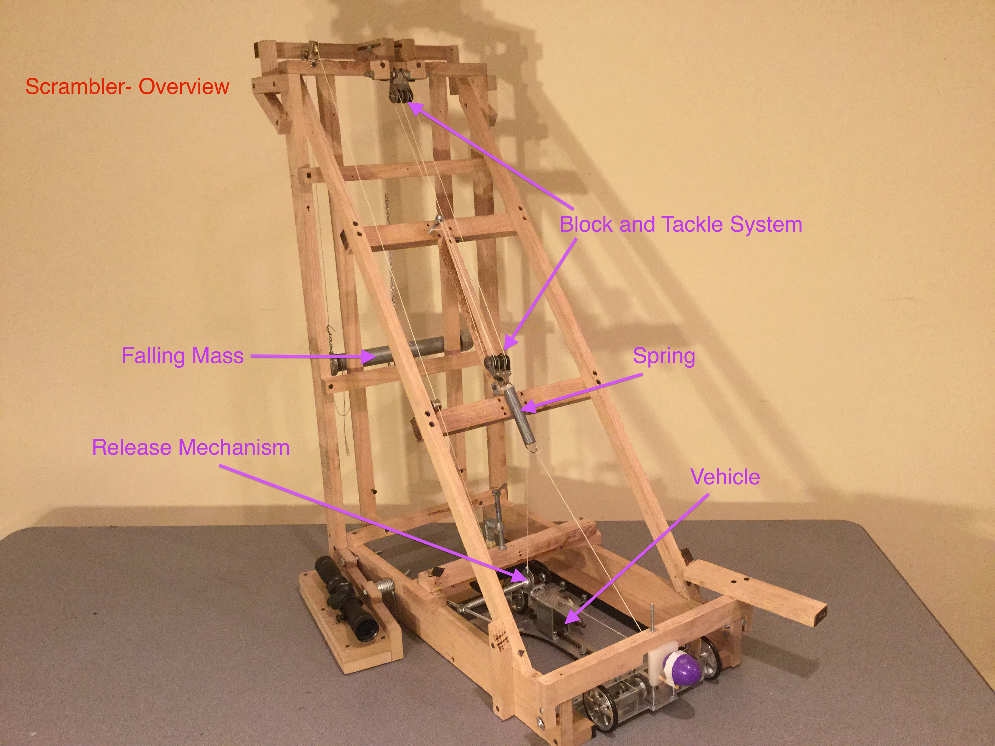
The device consists of a launcher, a vehicle, a scope for alignment, and a falling mass & release mechanism. As the mass falls, it extends and stores its energy in a spring. As the mass reaches the end of its travel and triggers the release mechanism, the vehicle is launched forward with the energy stored in the spring.
General Construction:
- Frame: manufactured out of oak to ensure the launcher was stable and heavy enough to withstand the tensile forces during launch.
- Falling Mass: consists of lead shot within a pipe, which creates a smaller profile. This allows the mass to fall a greater distance, which will result in more energy available for launching the vehicle.
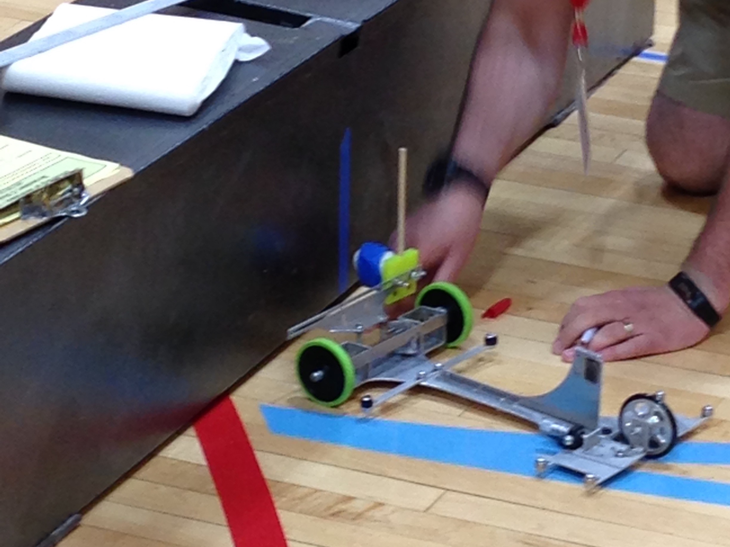
- Vehicle: created out of aluminum to be lightweight, able to withstand the tensile forces from the spring, and easily machinable.
- Spring: made out of music wire, giving it a greater elastic limit and a higher Young's Modulus.
To utilize the full gravitational potential energy (GPE) of the mass while reducing vehicle travel time, the entirety of this energy must be transferred prior to the 0.5m line (as timing only begins once the vehicle passes this point). As the mass falls at most 1m, its GPE cannot be directly transferred to the vehicle within 0.5m.
To overcome this, the GPE of the mass was firstly stored in an extension spring by means of a block and tackle system with an ideal mechanical advantage of 4. An IMA of 4 was chosen because, ideally, 1m/4 = 0.25m < 0.5m. This would bring the vehicle to its top speed before timing begins while reducing the overall dimensions and weight of the vehicle. I could have used an IMA of 2 to launch the vehicle exactly as it passes the timing point (1m/2=0.5m). However, this would force the vehicle to be at least 0.5m in length (as it needs to be pulled for this distance) and would therefore increase its weight.
Because the mass itself has a height, it realistically can fall 0.8m. This video (right) demonstrates how the spring elongates about 20 cm as the mass falls about 80 cm, demonstrating an IMA of 4 for the pulley system. As the mass is lowered, the tension in the string rises, evidenced by the rising frequency of the emitted sound as it is plucked.
A pin holding the mass is pulled out. As the mass reaches the end of its vertical travel, it pulls on and unscrews a C-clamp that holds the vehicle in place during the extension of the spring. The vehicle can launch once the clamp is no longer holding it in place.
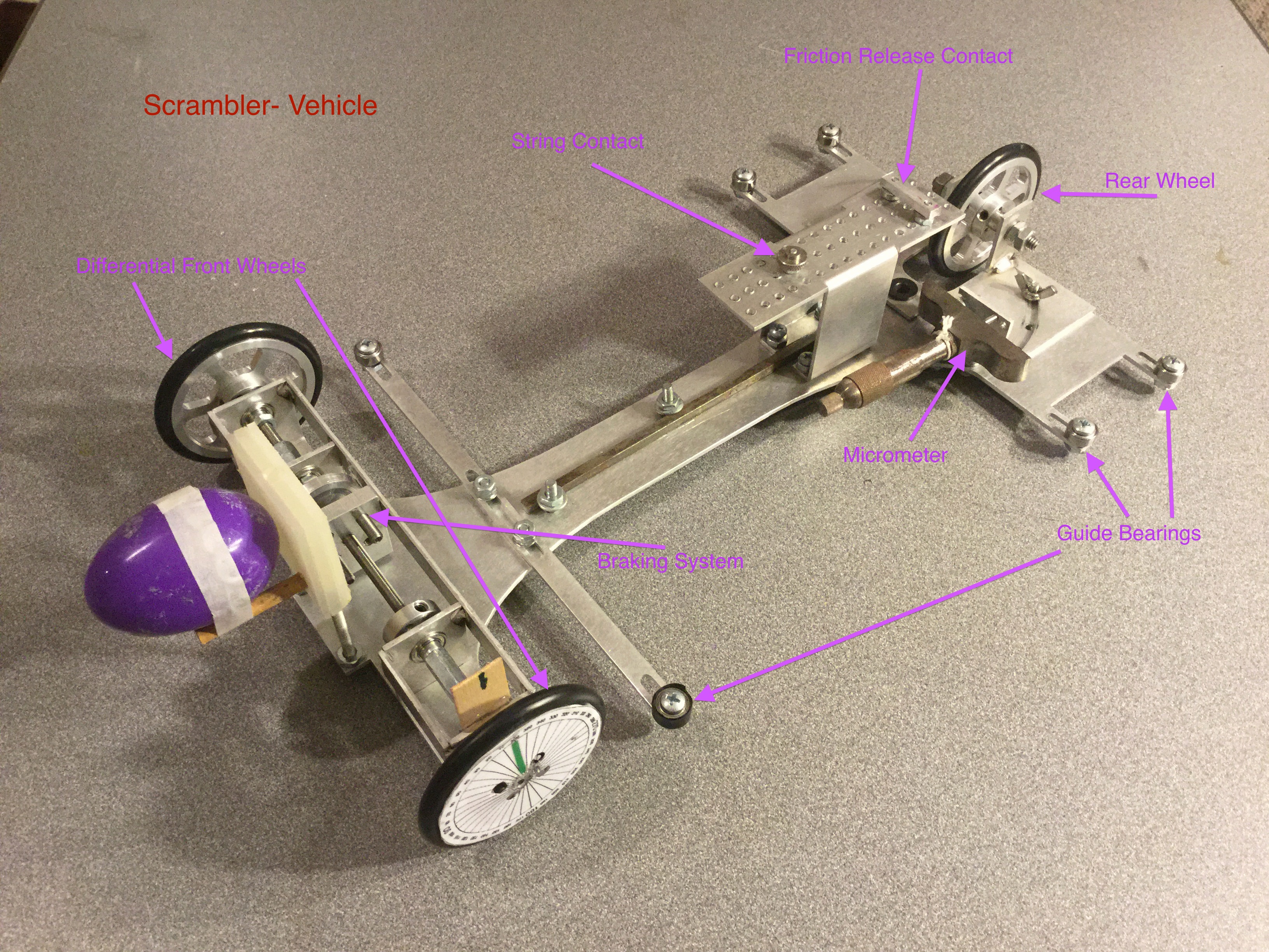
I designed the vehicle with the pulley system in mind. As I expected the mass to fall 80cm and elongate the spring by 20cm, I required a pulling distance of at least 20cm (i.e. the spring pulls the vehicle this amount). Taking into account the front and rear axles, the total vehicle length was ~30cm. Based on previous iterations of the vehicle, it was apparent that a length to width ratio of ~2:1 would prevent the car from turning unpredictably due to variations in the track surface, resulting in a width of 15cm.
The spring pulled on a “table” or, in the final iteration, a “fin”, that was situated on the vehicle. This added rigidity to the vehicle and also ensured that its main body would not feel the high tensile forces.
As the terminal barrier’s location is unknown prior to the competition, the vehicle must be built to travel and stop at a range of distances. A threaded axle and “locknut” style braking system was utilized for this.
However, instead of a typical locknut, a machined block with spring plungers was used. This block runs into a rotating disk along the same axis, after which the front axle would not be able to turn. The front axle was made to be differential to enable the front wheels to rotate at different speeds as they travel along the curved path.
Spring plungers were implemented to increase accuracy. They increase the time and decrease the force of the impulse imparted by the braking mechanism, making the vehicle less prone to skidding and allowing it to come to a more gradual, accurate stop.
Prior to the competition, over 300 trial runs were completed to collect data and understand the relationship between wheel turns and stopping distance.
The obstacle is always placed half-way between the start point and the center of the terminal barrier. Therefore, not only must the vehicle travel different distances, it must also follow different arcs.
To calibrate for this, the vehicle was designed with a single rear wheel that could pivot. The pivot amount was specified by extending a micrometer various lengths.
Similar to the distance calibration, trials runs were completed to collect data and understand the relationship between micrometer distance and arc radius.