Gravity Vehicle
The Problem
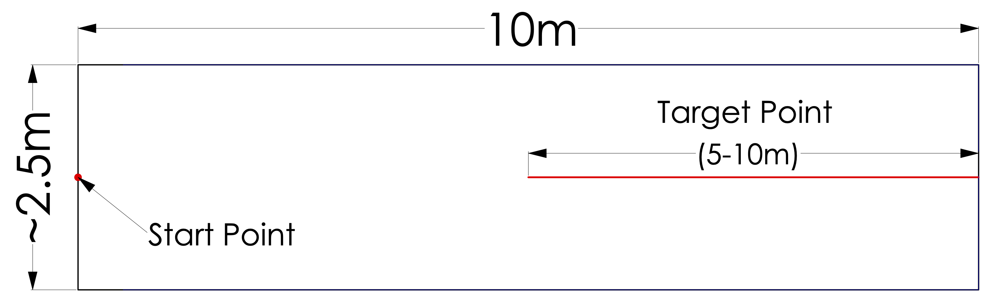
Design, build, and test one vehicle and ramp that uses gravitational potential energy as the vehicle’s sole means of propulsion to reach a Target Point as quickly, as accurately, and as close to a predicted time as possible.
The Target Distance is announced the morning of the competition and can be between 5-10m. The score calculation favors lower vehicle release heights, as higher velocities and faster times are harder to achieve.
Constraints:
- The vehicle’s mass must not exceed 1.5kg
- The system’s dimensions must be no greater than: W = 0.50m, L = 0.75m, H = 2.0m
- The measurement point on the vehicle is defined as the end of a bent paperclip
- No electrical or electronic devices may be used
- The vehicle must not be remotely controlled or tethered
Solution
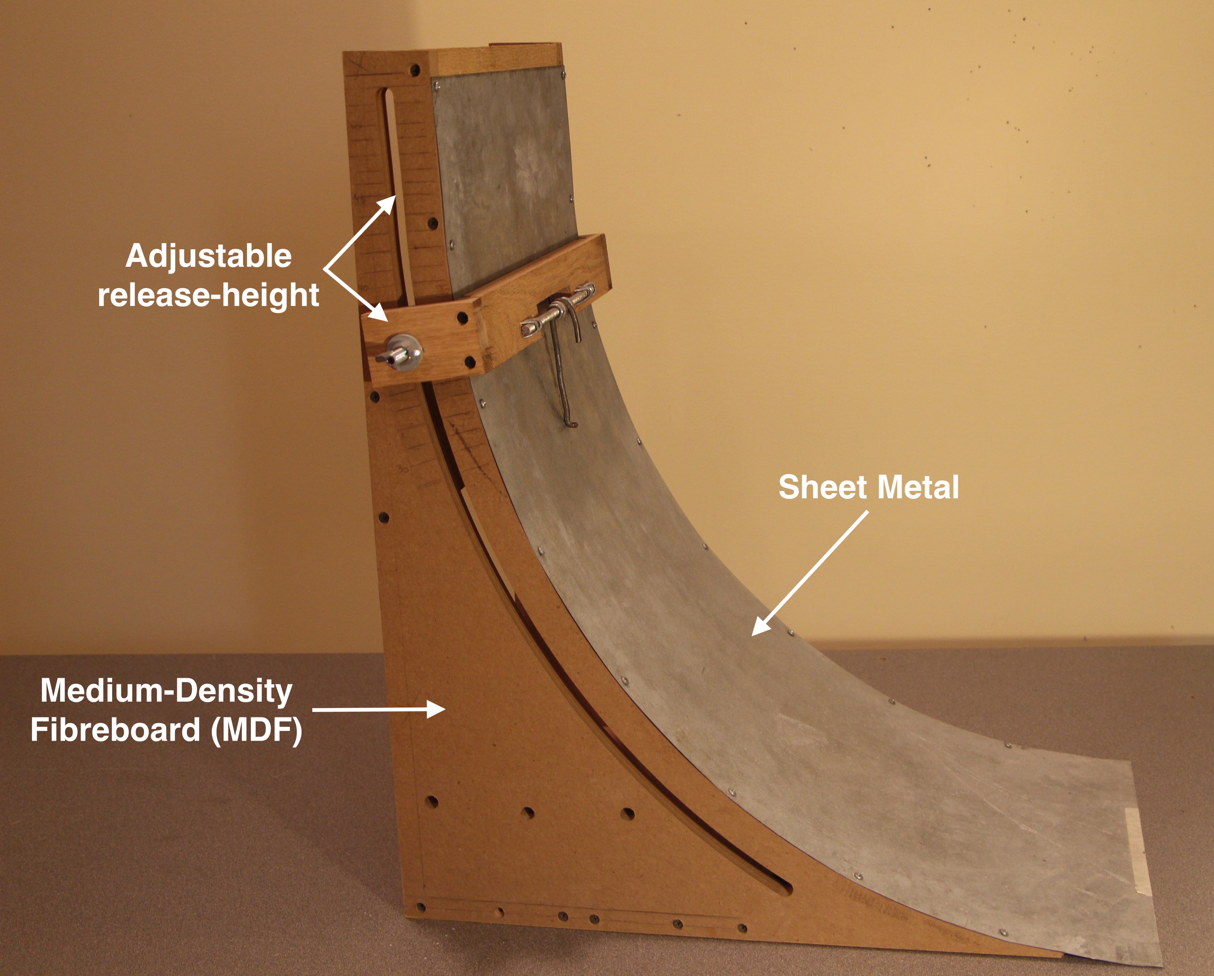
The shape of the ramp was designed to be a brachistochrone curve, as this is the curve of fastest decent and results in a decreased travel time.
As the rules favor a lower release height as well as a faster travel time (which are inversely related), each target distance has an ideal release height. To implement this, I created an adjustable release to optimize the total score for each distance (implemented with a release bracket and groove that follows the shape of the ramp). By curve-fitting data from over 200 trial runs, I determined the ideal release height for any assigned distance and the predicted times for each distance.
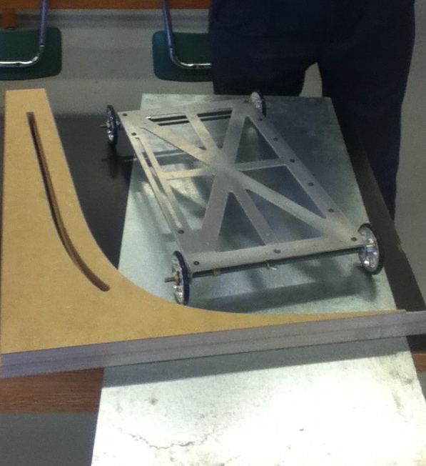
The vehicle was designed with a length to width ratio of roughly 2:1; from experience, this makes the vehicle less susceptible to turning unpredictably due to variations in the track surface.
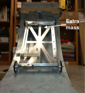
The frame was machined out of aluminum with minimal surface area to reduce its weight while being rigid enough to withstand the forces during launching and braking. By reducing the mass of the frame as much as possible, I was able to allocate the rest of the 1.5kg mass limit to the top of the vehicle. This increased the gravitational potential energy of the vehicle.
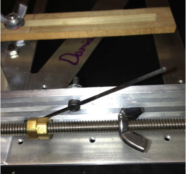
A threaded axle and lock-nut style braking system was used. In addition, a carbon fiber rod that crossed into the path of the locknut’s wing was implemented to increase the time and decrease the force of the impulse imparted by the braking mechanism. This made the vehicle less prone to skidding and allowed it to come to a more gradual, accurate stop.
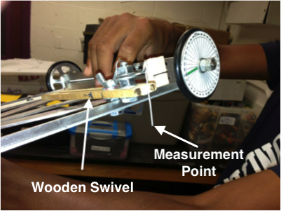
Parameters define the measurement point of the car to be the tip of a paperclip. The paperclip is on a swivel (by loosening the wing nut, the wooden swivel can freely extend to any point within its reach). As competitors are given two runs during competition, I can ensure a near perfect second run distance given that the target point is within the range of the sweeping paperclip.
These are example trial runs used to understand the relationships between wheel turns/travel distance and ramp height/travel time. Ultimately, we finished 6th place at the national competition.